Drive Wrench Assembly Slingco part nos. SAE08666, SAE09639, SAE10425, SAE10486, SAE10427, SAE13513, SAE11132, SAE14309
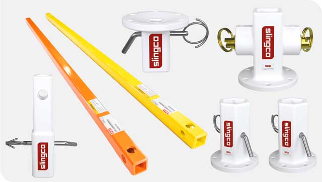
Thank you for using Slingco® products. This manual must be read and understood prior to operating this product. Special attention should be paid to the section ‘Safety Information’.
ATTENTION
READ and UNDERSTAND all of the instructions and safety information in this manual before operating or servicing this tool.
Failure to read and understand these warnings and safe handling instructions could result in severe personal injury or death.
Download this manual as PDF.
SAFETY INFORMATION
Work area safety
- Keep the area around the equipment clean and free of obstruction.
- Bystanders should stay clear of the work area to ensure safety.
Personal safety
- Stay alert while using the equipment to prevent serious injury. Do not use under the influence of drugs, alcohol or medications.
- Do not wear loose hair or clothes that may get caught while the equipment is in operation.
- Work safely. Ensure firm footing, be properly secured, and do not over-extend yourself while operating equipment.
Tool use and care
- DO NOT use this tool if there are any abnormailities or damage to any of its components.
- Inspect the tool before and after every use. Do not use this tool if it is damaged in any way. Ensure that all pins are secure. Be sure to inspect all hydraulic hoses and couplers for cracks, leaks, and wear.
- When having the tool repaired, always use factory Slingco replacement parts. Tools must be serviced and/or repaired by Slingco or a factory authorized service center.
Parts list for Drive Assembly
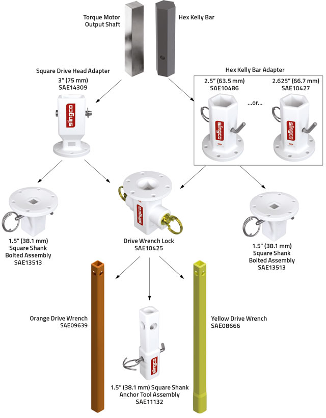
SAE08666 - Yellow Drive Wrench
SAE09639 - Orange Drive Wrench
SAE10425 - Drive Wrench Lock
SAE10427 - 2-5/8” Hex Kelly Bar Adapter
SAE10486 - 2-1/2” Hex Kelly Bar Adapter
SAE11132 - 1-1/2” Square Shank Anchor Tool Assembly
SAE13513 - 1-1/2” Square Shank Bolted Assembly
SAE14309 - 3” (75 mm) Square Drive Head Adapter
SAE11531 - Drive Wrench Lock Pin Assembly Parts Kit for SAE10425
SAE11532 - Hex Kelly Bar Adapter Bent Arm Pins and Coil Lock Kit for SAE10486 and SAE10427
SAE11533 - Fastener Kit for SAE14309, SAE10486, SAE10427, SAE13513 and SAE10425
SAE14491 Square Shank Adapters, Bent Arm Pin and Coil Lock Kit for SAE11132 and SAE13513.
SAE14484 Square Drive Head Adapter Replacement Pin for SAE14309
LAB12436 - Label Kit for SAE09639
LAB12437 - Label Kit for SAE08666
LAB12519 - Warning Label for SAE10425, SAE10486, SAE10427 and SAE14309
LAB12520 - Warning Label for SAE13513 and SAE11132
Torque rating of tools
| Part no. | Torque rating ft-lb (N-m) |
|---|---|
| SAE10486 | 10,000 (13,558.18) |
| SAE10427 | 10,000 (13,558.18) |
| SAE10425 | 10,000 (13,558.18) |
| SAE09639 | 10,000 (13,558.18) |
| SAE08666 | 10,000 (13,558.18) |
| SAE11132 | 7,000 (9,490.73) |
| SAE13513 | 7,000 (9,490.73) |
| SAE14309 | 10,000 (13,558.18) |
Assembling components
KELLY BAR ADAPTER ASSEMBLY
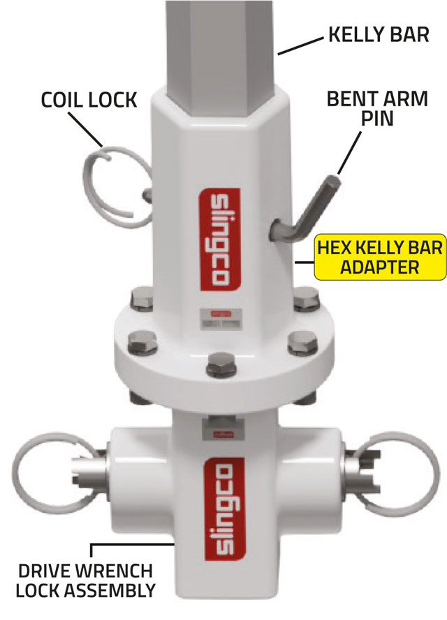
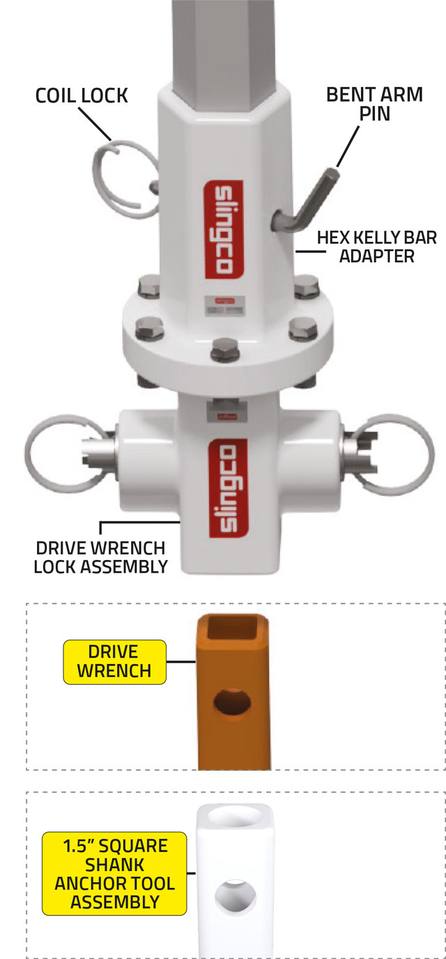
The Drive Wrench Lock Assembly and 1.5” (38 mm) Square Shank Bolted Assembly are attached to the Hex Kelly Bar Adapter via
the bolt circle on the flange of the Adapter.
To determine which Hex Kelly Bar Adapter you need, first measure your Kelly Bar across the flats for the correct Adapter size. Then determine the maximum torque load from your digger motor. Be sure not to exceed the maximum torque load rating of
the Adapter being used. (See table on this page.)
The Hex Kelly Bar Adapters have the size accepted cast onto the outside of the casting. Check that the Adapter you have matches the size of your Kelly Bar.
Check the end of the Kelly Bar for wear. If the Kelly Bar is worn replace it. A minimum of 3” (75mm) of hex or square engagement is required between the Kelly Bar and the attached tool or the Bent Arm Pin may wear prematurely and become damaged. (Replacement Bent Arm Pins can be ordered by referencing part #SAE11532.)
Once the correct Hex Kelly Bar Adapter is chosen and the Kelly Bar is checked for wear, slide the Kelly Bar into the socket of the Hex Kelly Bar Adapter. Pin the Hex Kelly Bar Adapter in place with the Bent Arm Pin provided. Lock the Bent Arm Pin in place with the Coil Lock, which is inserted in the hole of the bent arm pin.
IMPORTANT
Each connection point is a potential pinch hazard. Adequate hand protection should be worn at all times while operating or assembling the components.
| Part no. | Adapter size in (mm) |
Torque rating of tools ft-lb (N-m) |
Bolt circle diameter in (mm) |
|---|---|---|---|
| SAE10486 | 2.5 (63.5) | 10,000 (13,558.18) | 5.25 (133.35) |
| SAE10427 | 2.625 (66.8) | 10,000 (13,558.18) | 5.25 (133.35) |
DRIVE WRENCH AND 1.5” (38 mm) SQUARE SHANK BOLTED ASSEMBLY
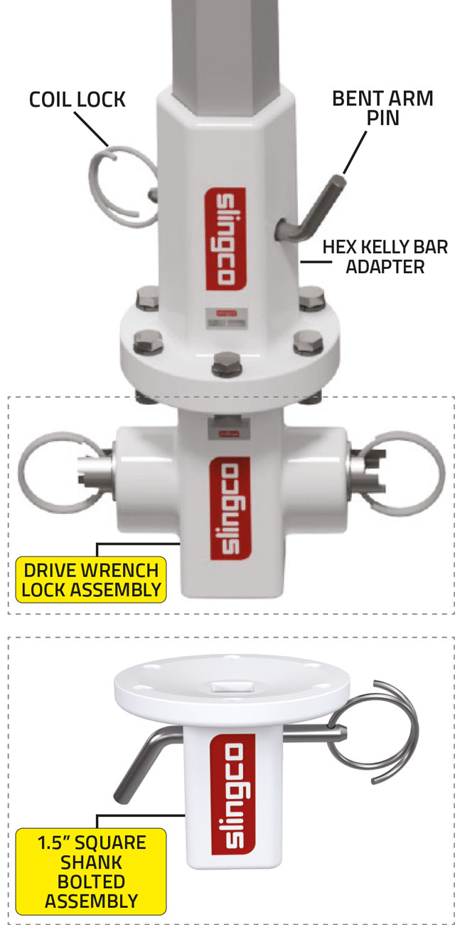
Using the included bolts, lockwashers and nuts, bolt the Drive Wrench Lock Assembly (shown in main diagram opposite), or the 1.5” (38 mm) Square Shank Bolted Assembly (shown below main diagram), to the Hex Kelly Bar Adapter.
The bolts provided with each Drive Wrench Lock Assembly and 1.5” (38 mm) Square Shank Bolted Assembly are hex head zinc plated, and are the appropriate length for attachment to another flange of equal thickness.
Tighten the bolts using a star pattern to the recommended torque values shown in the table below.
When installing hardware ensure there is a lockwasher on either flange.
DO NOT USE fasteners manufactured by another manufacturer. Only Slingco supplied fasteners should be used!
IMPORTANT
Each connection point is a potential pinch hazard. Adequate hand protection should be worn at all times while operating or assembling the components.
| Part no. | Torque rating of tools ft-lb (N-m) |
Bolt circle diameter in (mm) |
Bolt diameter (in) mm |
Grade | Recommended bolt torque values ft-lb (N-m) |
|---|---|---|---|---|---|
| SAE10425 | 10,000 (13,558.18) | 5.25 (133.35) | 0.5 (6.35) | 5 | 75 (101.69) |
| SAE13513 | 7,000 (9,490.73) | 5.25 (133.35) | 0.5 (6.35) | 5 | 75 (101.69) |
DRIVE WRENCH AND 1.5” (38 mm) SQUARE SHANK ANCHOR TOOL ASSEMBLY
To install the Drive Wrench or 1.5” (38 mm) Anchor into the Drive Wrench Lock, pull the Coil Locks outward, while twisting counter-clockwise, until they are in the outermost position. Be sure both pins are fully engaged before proceeding.
Insert the Drive Wrench (shown top right) or 1.5” (38 mm) Square Shank Anchor Tool Assembly (shown bottom right).
Capture the Drive Wrench or 1.5” (38 mm) Square Shank Anchor Tool Assembly with the Locks by twisting the Coil Lock clockwise until in the inside position.
Note: The Drive Wrench Lock Coil Locks have three positions in which they operate. The inside position shown holds both the Drive Wrench and the Anchor Rod.
Note: For the 1.5” (38 mm) Square Shank Anchor Tool Assembly the middle position is not necessary.
To install a square anchor shank into 1.5” (38 mm) Square Shank Anchor Tool Assembly , remove Coil Lock from Bent Arm Pin and remove from tool. Insert Anchor and align the holes of the Anchor and Tool. When this is done, replace the Bent Arm Pin and Coil Lock.
See diagram below.
| Part no. | Torque rating of tools ft-lb (N-m) |
Color |
|---|---|---|
| SAE08666 | 10,000 (13,558.18) | Yellow |
| SAE09639 | 10,000 (13,558.18) | Orange |
| SAE11132 | 7,000 (9,490.73) | White |
SQUARE DRIVE HEAD ADAPTER ASSEMBLY
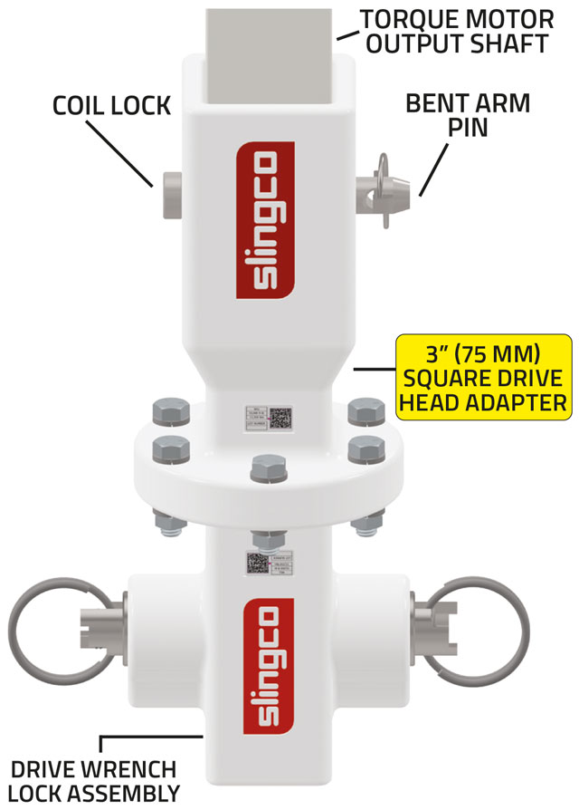
The Drive Wrench Lock Assembly and 1.5” (38 mm) Square Shank Bolted Assembly are attached to the 3” (75 mm) Square Drive
Head Adapter via the bolt circle on the flange of the Adapter.
Determine the maximum torque load from your torque motor. Be sure not to exceed the maximum torque load rating of the Adapter being used. (See table below.)
Check the end of the Square Drive Head for wear. If the Square Drive Head is worn, replace it. A minimum of 2” (51 mm) of square engagement is required between the Drive Head and the attached tool or the Clevis Pin may wear prematurely and become damaged. (Replacement Clevis Pins can be ordered by referencing part #SAE14484.)
Pin the Square Drive Head Adapter in place with the Bent Arm Pin provided. Lock the Bent Arm Pin inplace with the Coil Lock, which is inserted in the hole of the bent arm pin.
| Part no. | Adapter Size in (mm) |
Torque rating of tools ft-lb (N-m) |
Bolt Circle Diameter in (mm) |
|---|---|---|---|
| SAE14309 | 3 (75) | 10,000 (13,558.18) | 5.25 (133.35) |
Drive Wrench Lock operation
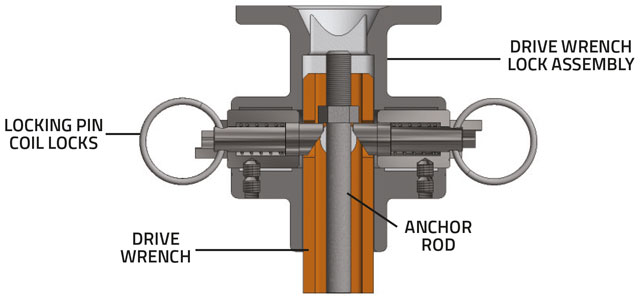
The Drive Wrench Lock Assembly coil locks have three positions which they operate. The inside position shown below holds both the Drive Wrench and the anchor rod.
The middle position shown releases the anchor rod ONLY.
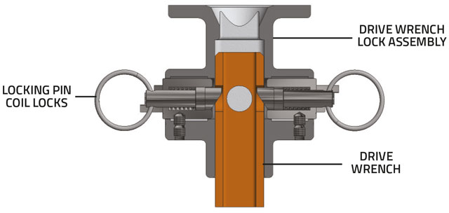
The outside position shown releases the Drive Wrench. This position is also ready to accept the Drive Wrench.
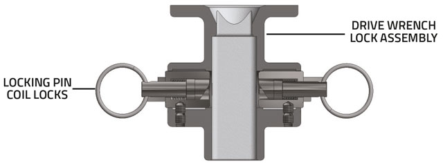
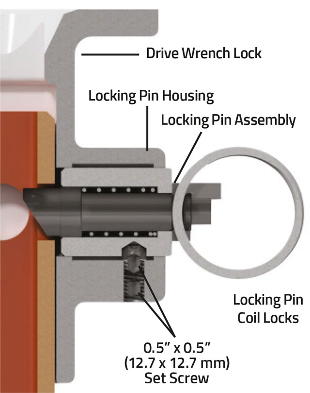
If the Locking Pin Assembly becomes damaged, remove the assembly by disassembling the set screws and pulling on the Locking Pin Coil Locks. Replace the Locking Pin Assembly with SAE11531, new set screws are included.
Insert the Locking Pin Assembly into the Locking Pin Housing. Align the ‘V’ on the Locking Pin Housing with the ‘V’ on the Locking Pin Assembly. Once the ‘Vs’ are
aligned, slide the Locking Pin Assembly until the indentation is underneath the Set Screw holes in the Locking Pin Housing.
Coat the thread of the first 1/2” x 1/2” (12.7 x 12.7 mm) set screw with Loctite RC 680 and screw in place/ Then coat the second 1/2” x 1/2” (12.7 x 12.7 mm) set screw with Loctite RC 680 and screw in place. The set screw must be seated in the indentation of the Locking Pin Assembly in order to hold it securely in the Drive Wrench Lock Assembly. See image for reference.
Tighten the set screws to a maximum 15-20 ft-lb (20.34-27.12 N-m) torque. If you have questions regarding the operation of the Drive Wrench Lock Assembly, please
contact your local Slingco office.
WARNING
Any loose parts may dislodge and fly when in operation. DO NOT OPERATE with any loose components or parts.
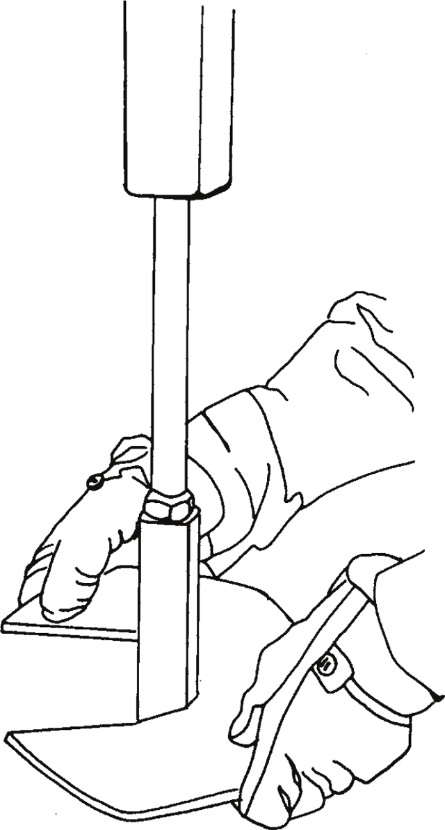
Installing Anchor Rod
Anchor hub & rod installation
Align the Anchor Hub with the Drive Wrench so that the two can telescope together.
Lock the Anchor Rod into place with a strong upward motion. This will cause the Anchor Rod to lock into place in the Drive Wrench Lock Assembly. Be sure to check to see if the Drive Wrench and Anchor Rod are securely held into place. If so, the tool string is ready to use.
Ensure that the tools in use are the appropriate size and rating for your particular application. Use the table below for more information.
IMPORTANT
Each connection point is a potential pinch hazard. Adequate hand protection should be worn at all times while operating or assembling the components.
| Part no. | Torque rating of tools ft-lb (N-m) |
Drive Wrench color | Hub size in (mm) |
Shaft size in (mm) |
|---|---|---|---|---|
| SAE08666 | 10,000 (13,558.18) | Yellow | 2.5 (63.5) | 1.5 (38.1) |
| SAE09639 | 10,000 (13,558.18) | Orange | 2.25 (77.15) | 1.375 (34.93) |
Maintenance and inspection
MAINTENANCE & INSPECTION OF DRIVE WRENCH ASSEMBLY COMPONENTS
The Drive Wrench Assembly parts require routine inspection and maintenance.
All parts, bolts, pins and fasteners used in the assembly should be inspected for excessive wear and corrosion prior to each use. Any bent or damaged parts, bolts, pins, and fasteners SHOULD NOT BE USED AND SHOULD BE IMMEDIATELY REPLACED.
Failure to maintain the Drive Wrench Assembly could result in system failure below stated ratings, causing damage to the system, as well as potential injury and damage to property.
Each bolt in the Drive Wrench Assembly should be inspected for tightness and torque as noted throughout this manual. DO NOT USE until all bolts are securely tightened.
Replacement bolts, pins, and fasteners are available from Slingco. ONLY SLINGCO REPLACEMENT PARTS SHOULD BE USED.
During anchor installation, keep Drive Wrench Assembly in alignment with the anchor being installed, in order to prevent uneven wear and damage to the system. Misalignment puts additional stress at the point where the anchor rod connects to the drive wrench. This could potentially split the drive wrench, causing system failure.
If the Drive Wrench becomes extremely twisted, DO NOT USE AND REPLACE IMMEDIATELY! The strength of the Drive Wrench is reduced significantly once twisting occurs.
Locking Pin Assemblies and warning labels are available from Slingco if needed. Replace any and all warning labels if they become damaged or inadvertently removed.
To replace labels, clean area with wire brush until clean and all old labels are removed. Once all pieces of old label are removed and surface is clean, place new labels so they are readable by the user.
Slingco makes no warranty, express or implied, with respect to this product nor with respect to its specifications. In no event shall Slingco be liable for any direct, indirect, punitive, incidental, special consequential damages to property or life, whatsoever, arising out of or connected with the use or misuse of this product. This product is intended for use by qualified professionals having adequate knowledge of its proper use.
Version: September 2023 - v1.6.